Lab 2 — Example Results
Week 7 · Spring 2026
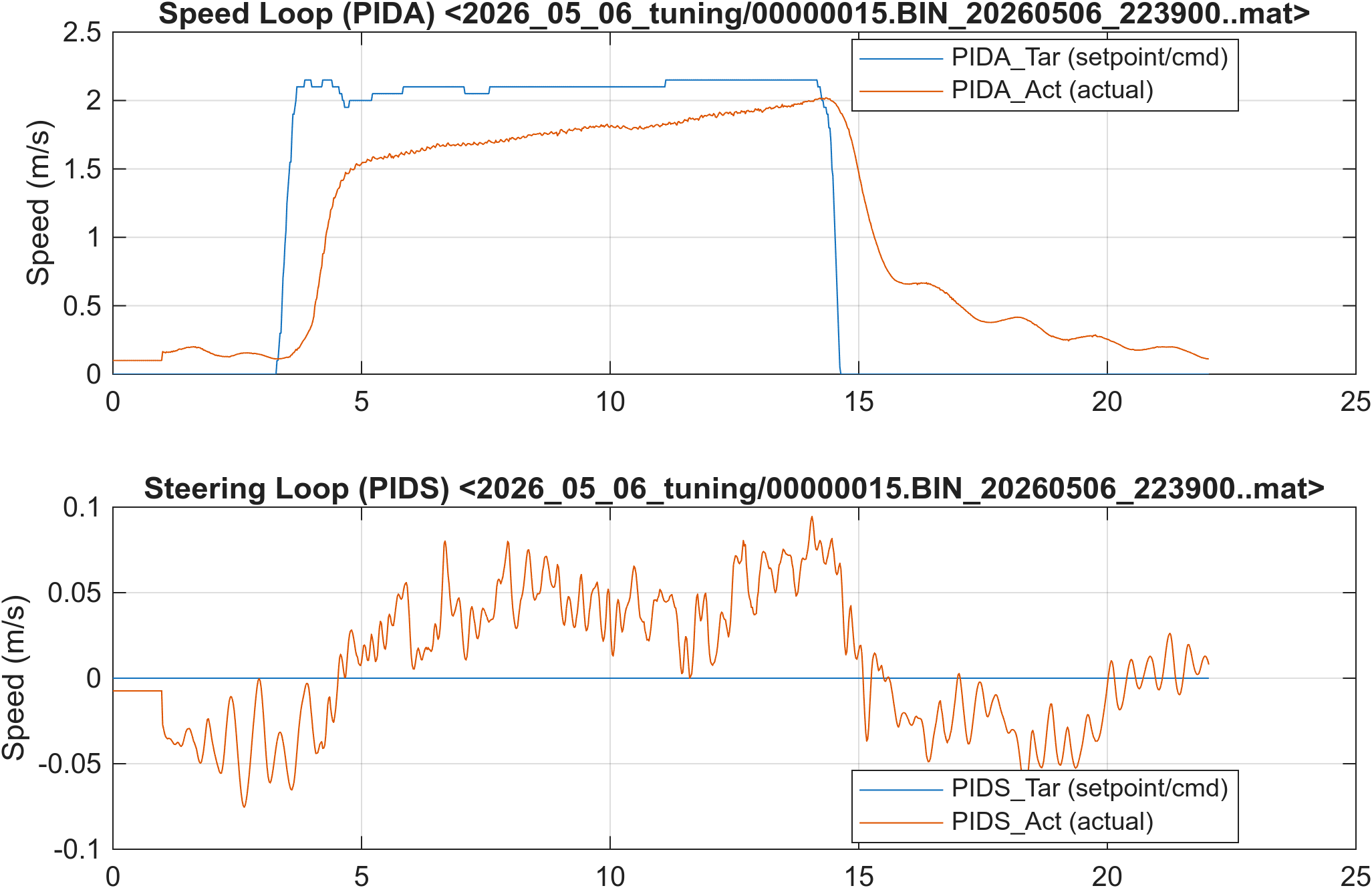
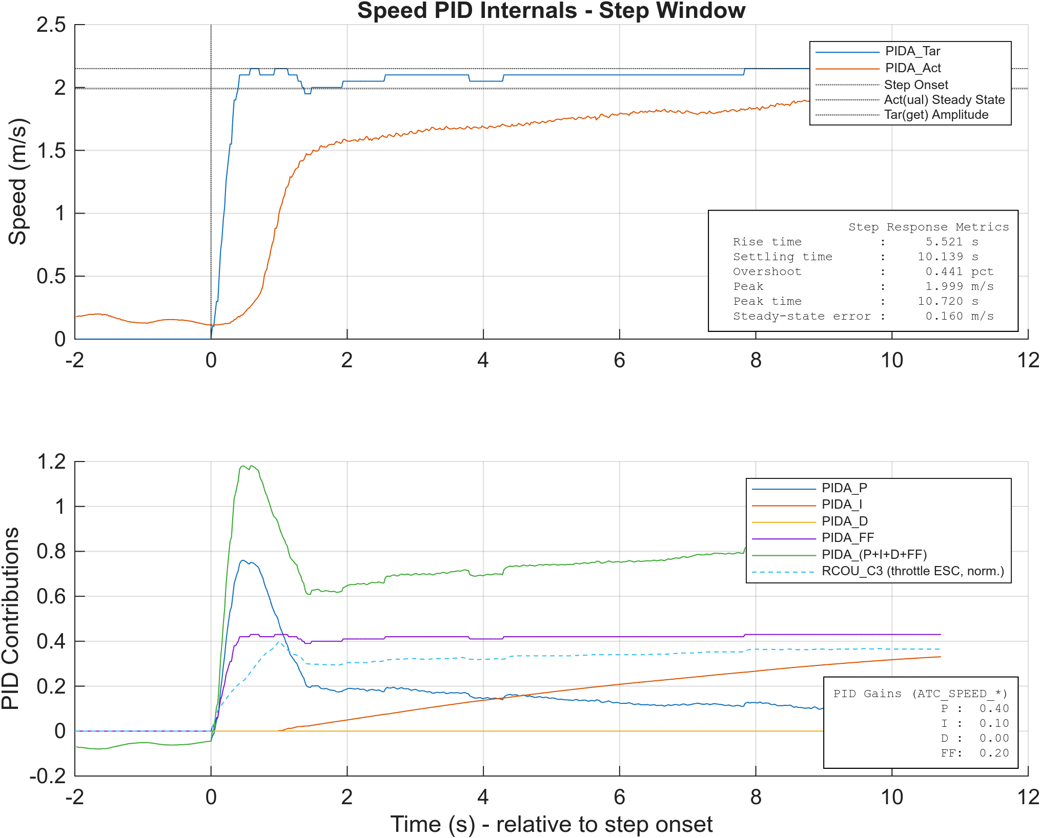
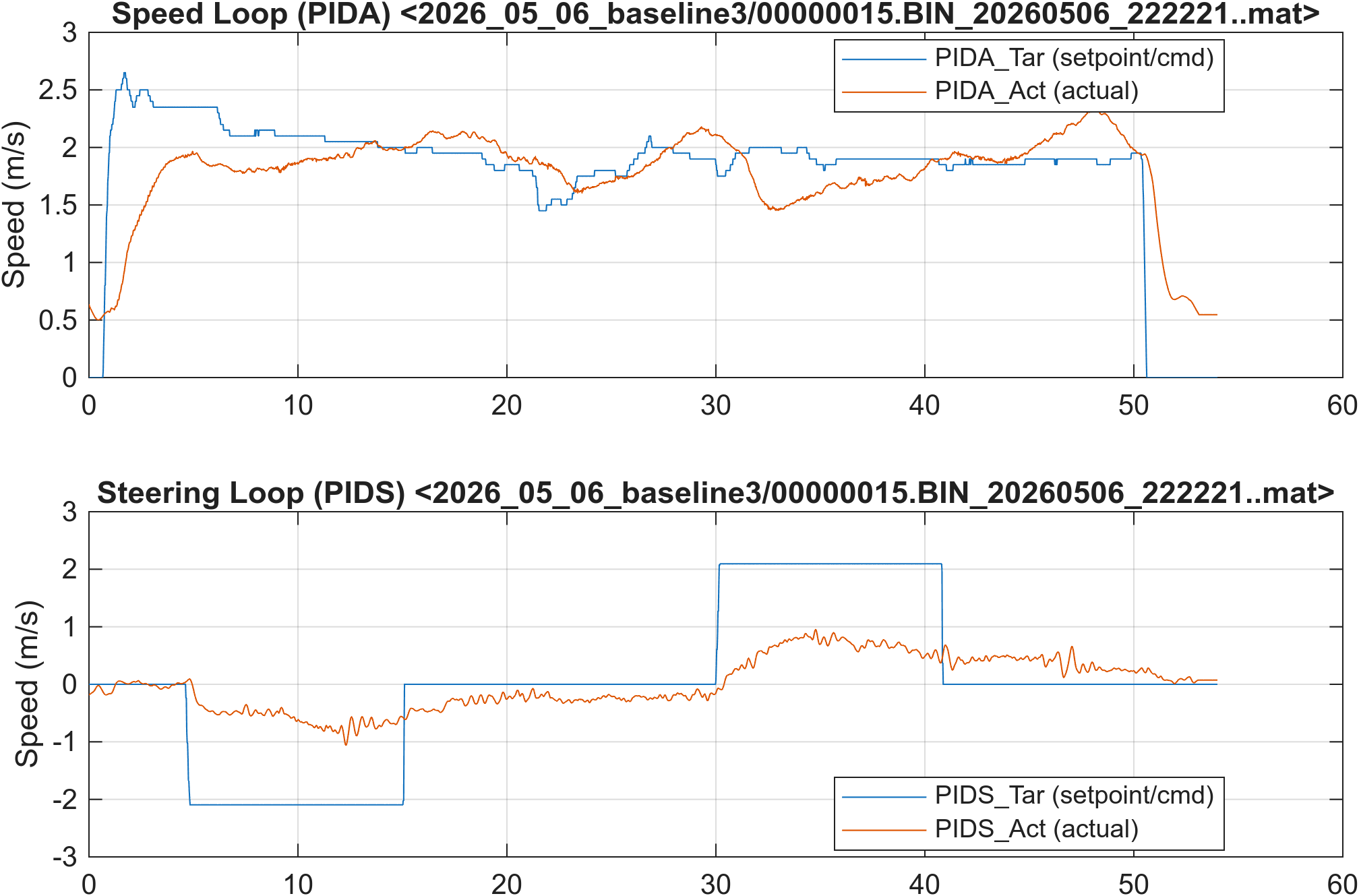
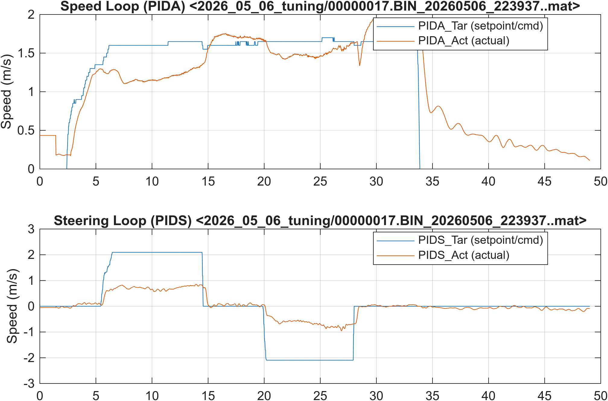
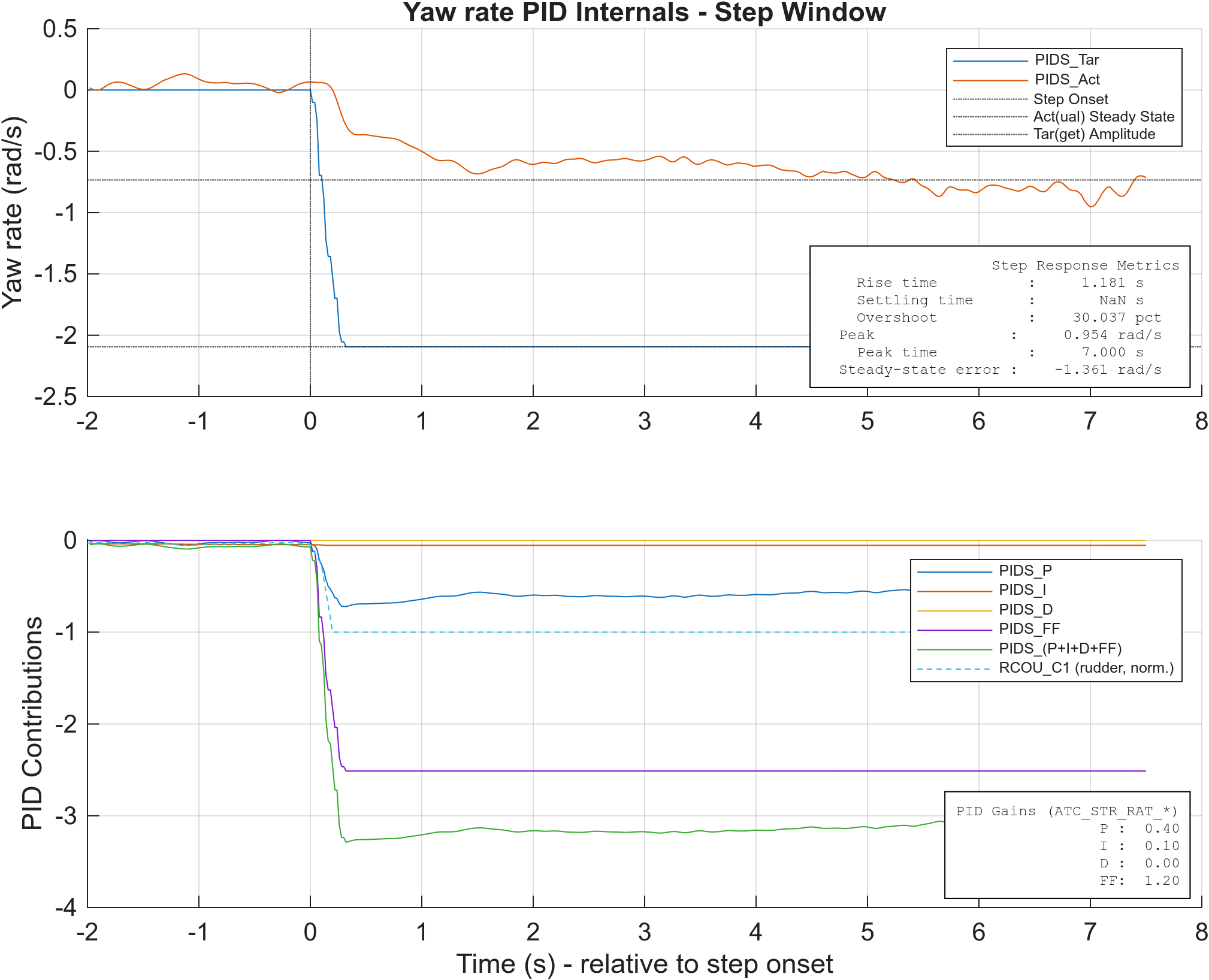
Example step-response figures from the three experiments (Base, FeedForward, Tuned) for the speed and yaw-rate channels. Each case has two figures:
- Timeseries — setpoint, measured response, and actuator command across the full step window.
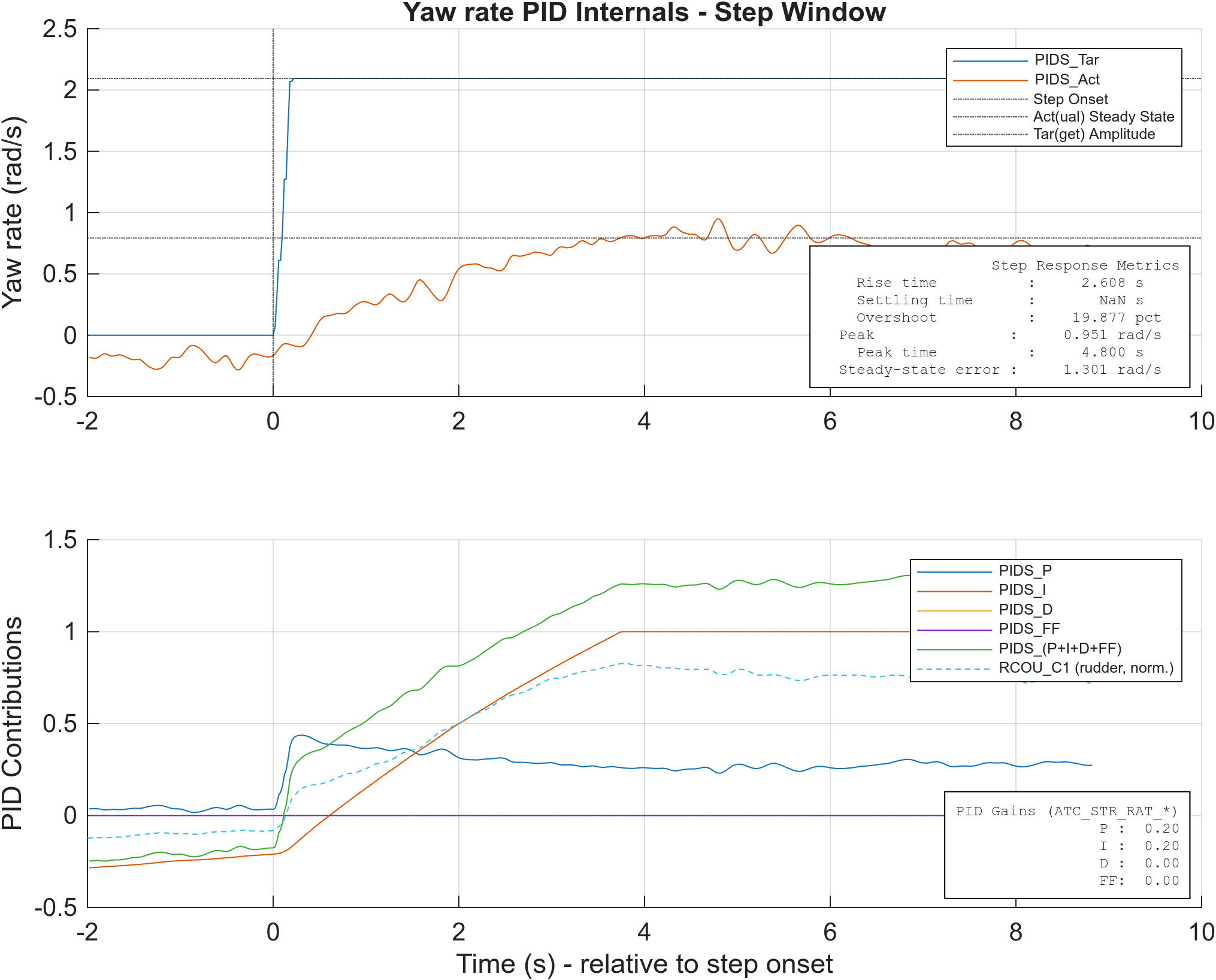
- PID internals —
Tar/Actwith metrics text box (top), and the per-term breakdown (P,I,D,FF) plus the actuator command (bottom).
A separate integrator-windup demonstration on the Base/yaw run shows what happens when the controller is allowed to hold the step long enough for the I term to wind up.
Speed Channel
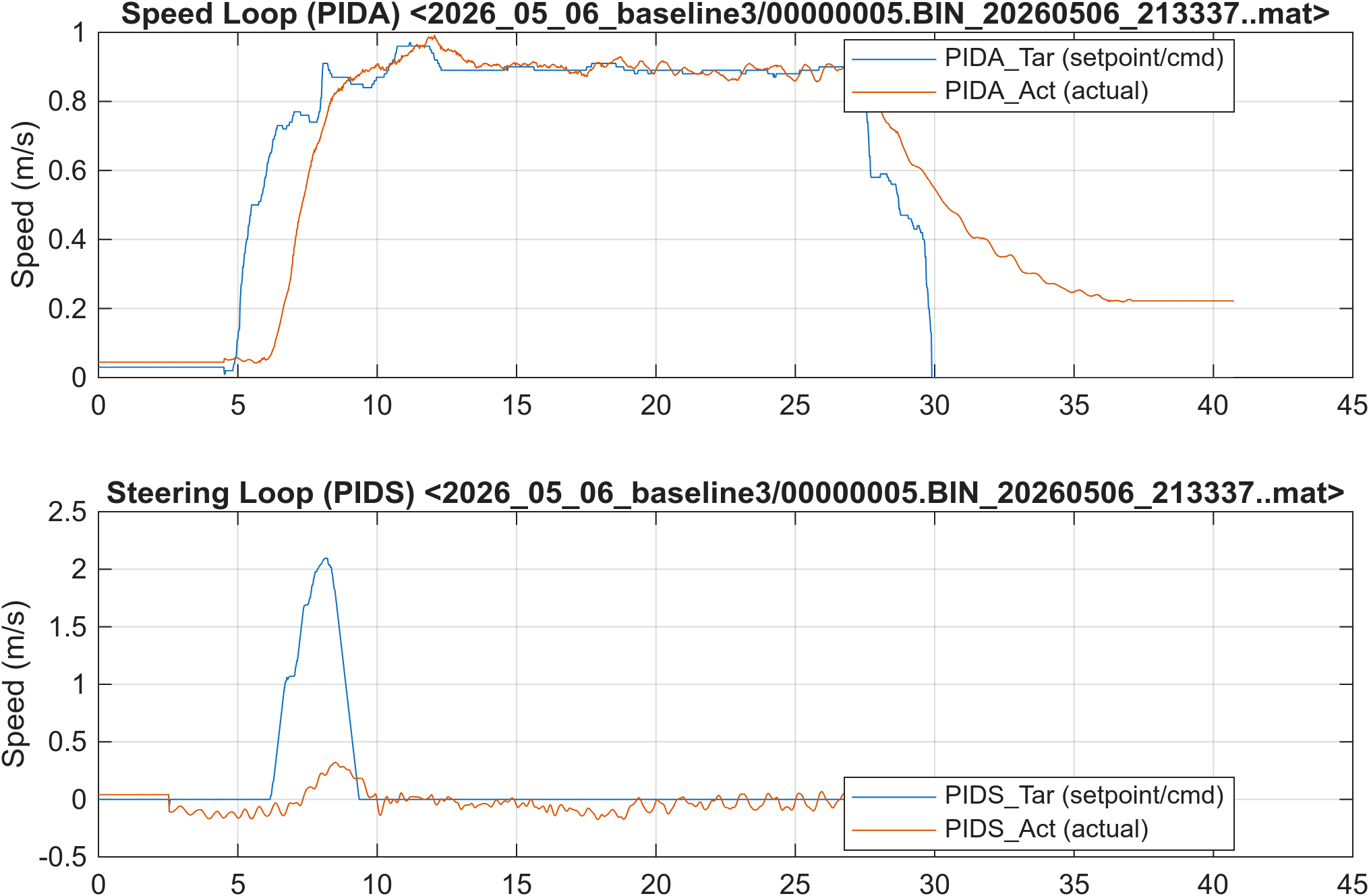
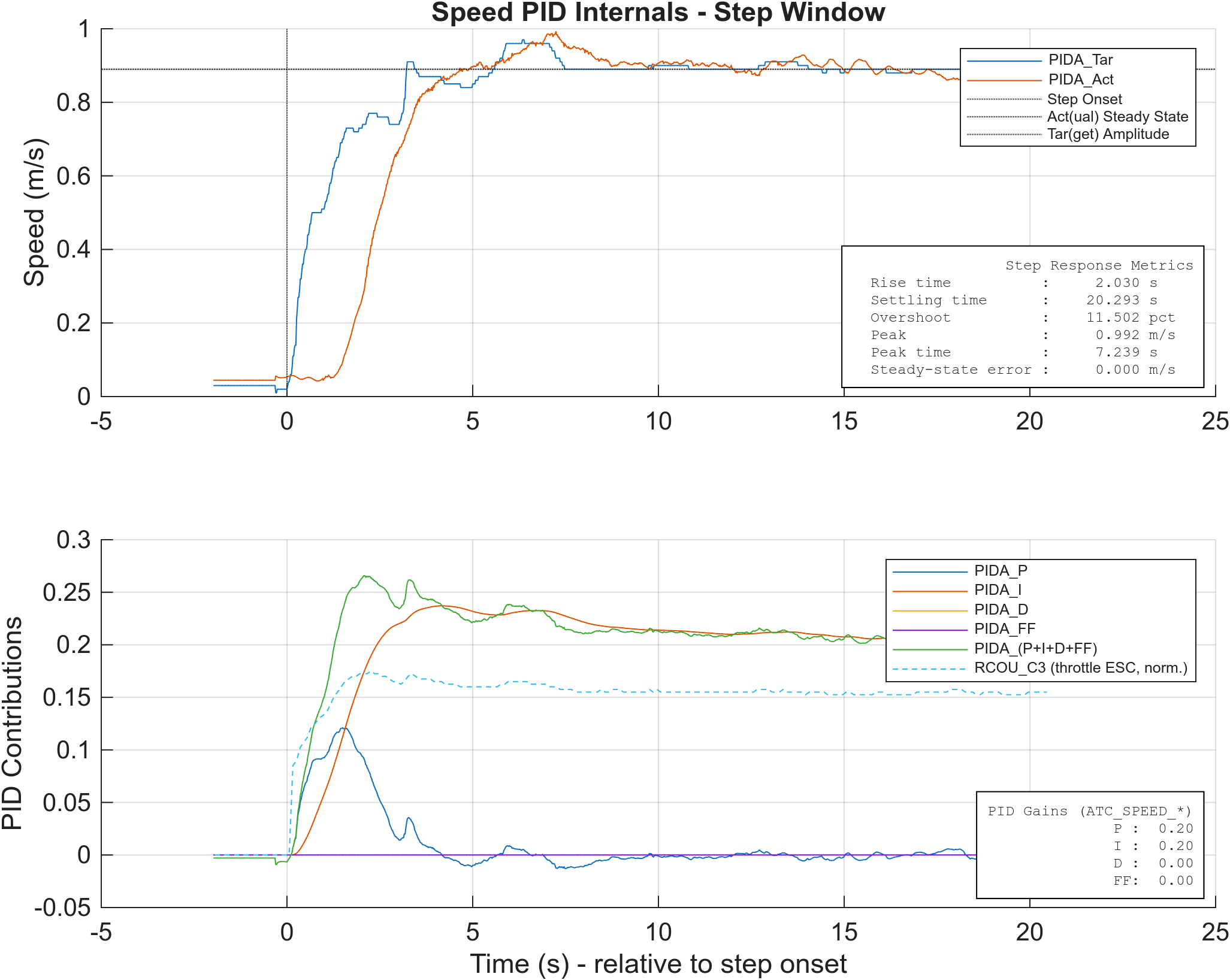
Base - Speed
ArduRover stock PID gains, FF off, rate limiters off, throttle baseline off. The reference against which FeedForward and Tuned are compared.
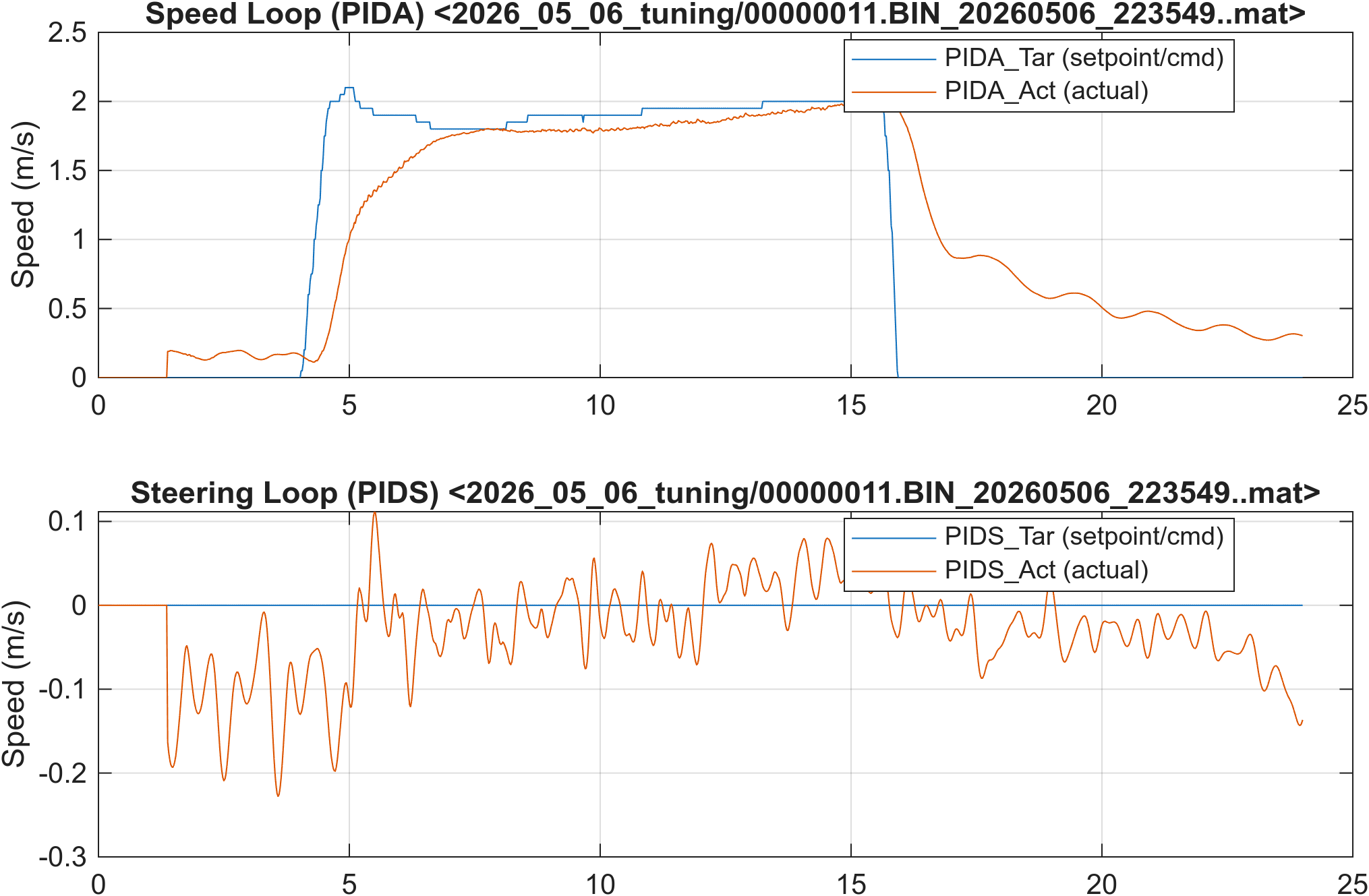
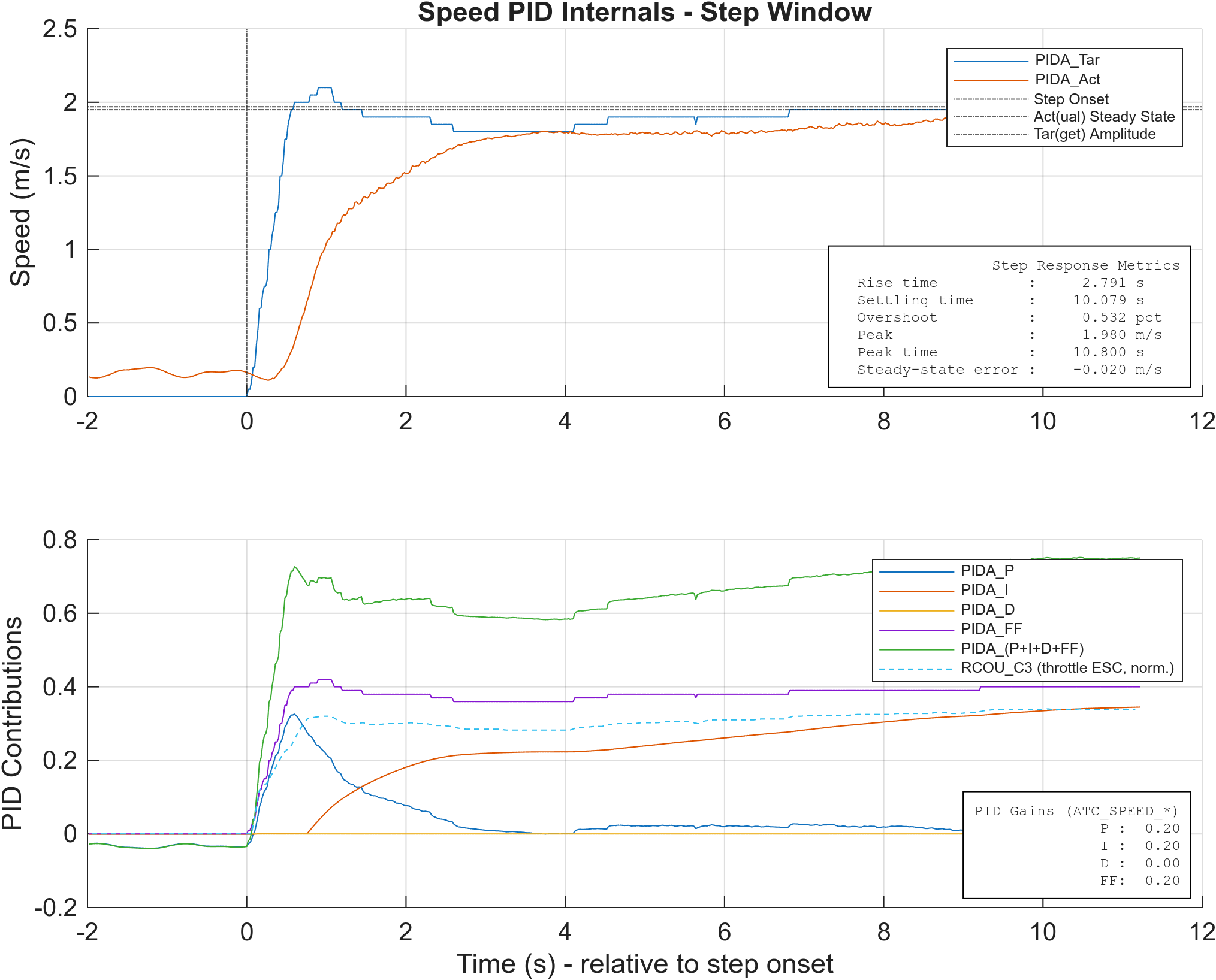
Feedforward - Speed
Tuned - Speed
Yaw-rate (Steering) Channel
Base - Yaw-rate
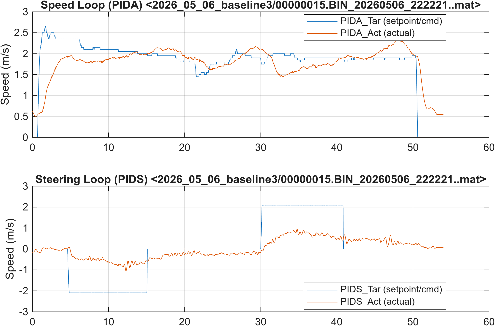
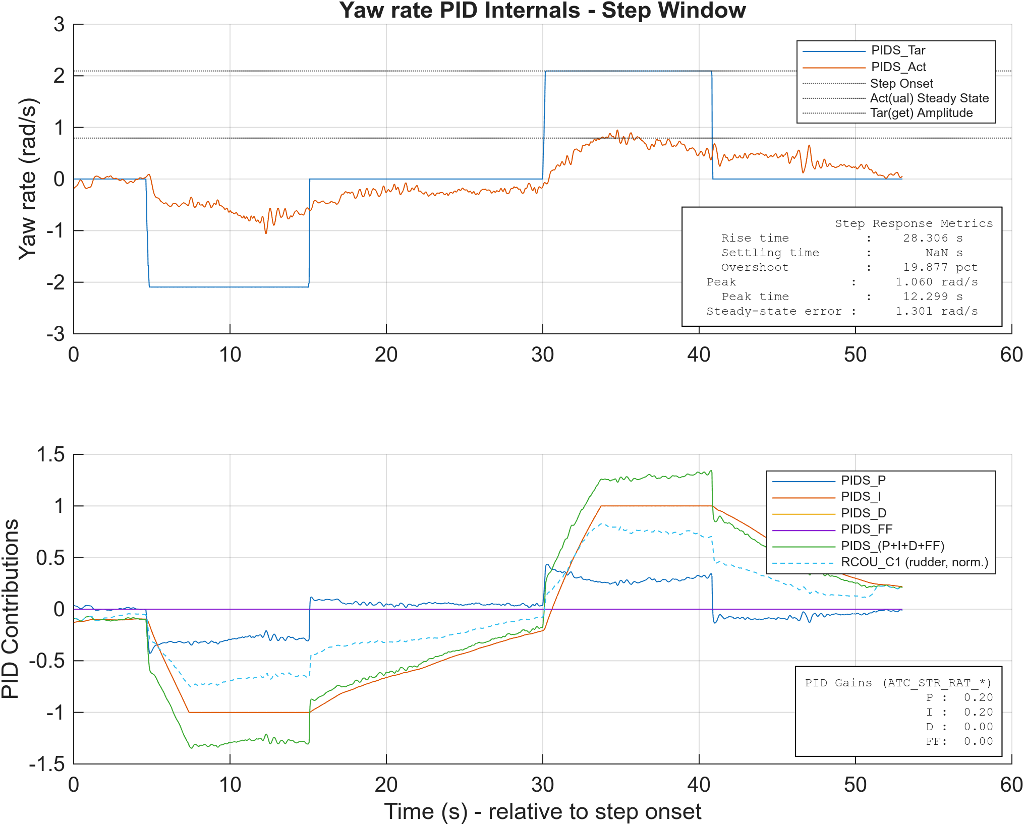
Known setup issue in this dataset: the baseline parameter file shipped with ACRO_TURN_RATE = 360 deg/s (≈ 6.28 rad/s), well above what the boat can physically achieve. Full-stick yaw commands therefore mapped to an unrealistically large setpoint, and the measured yaw rate plateaus far below the commanded value — visible as a large steady-state error in the figures and the metrics table. The procedure now has students reduce ACRO_TURN_RATE to a value the boat can actually track.
Base - Yaw-rate (integrator windup demonstration)
The same Base/yaw configuration as above, but the step input is held long enough for the integrator to wind up. The delayed recovery on the step-back illustrates classic I-term windup.
Feedforward - Yaw-rate
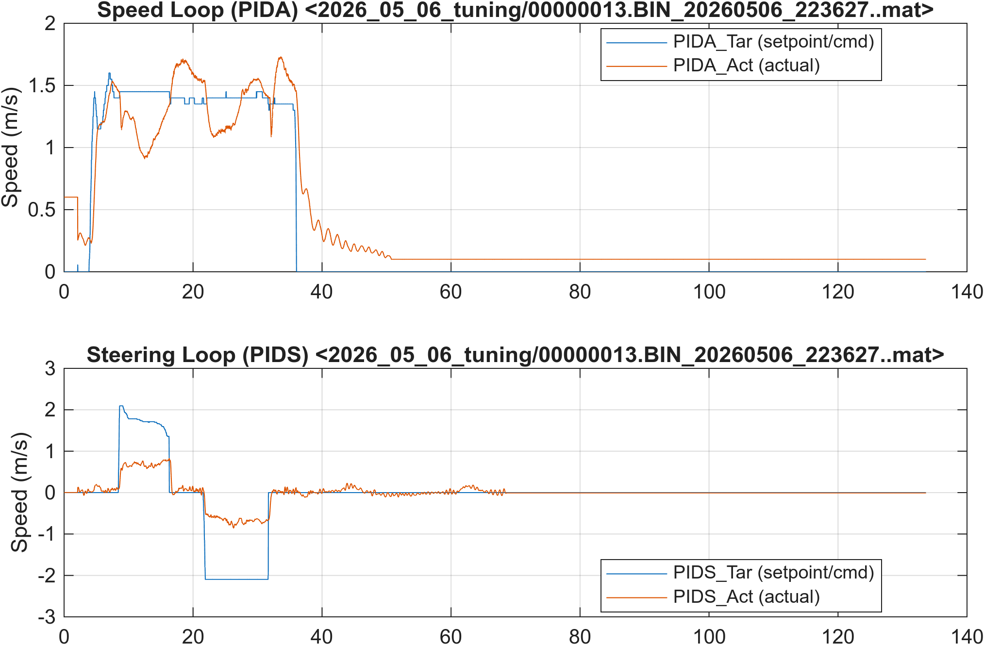
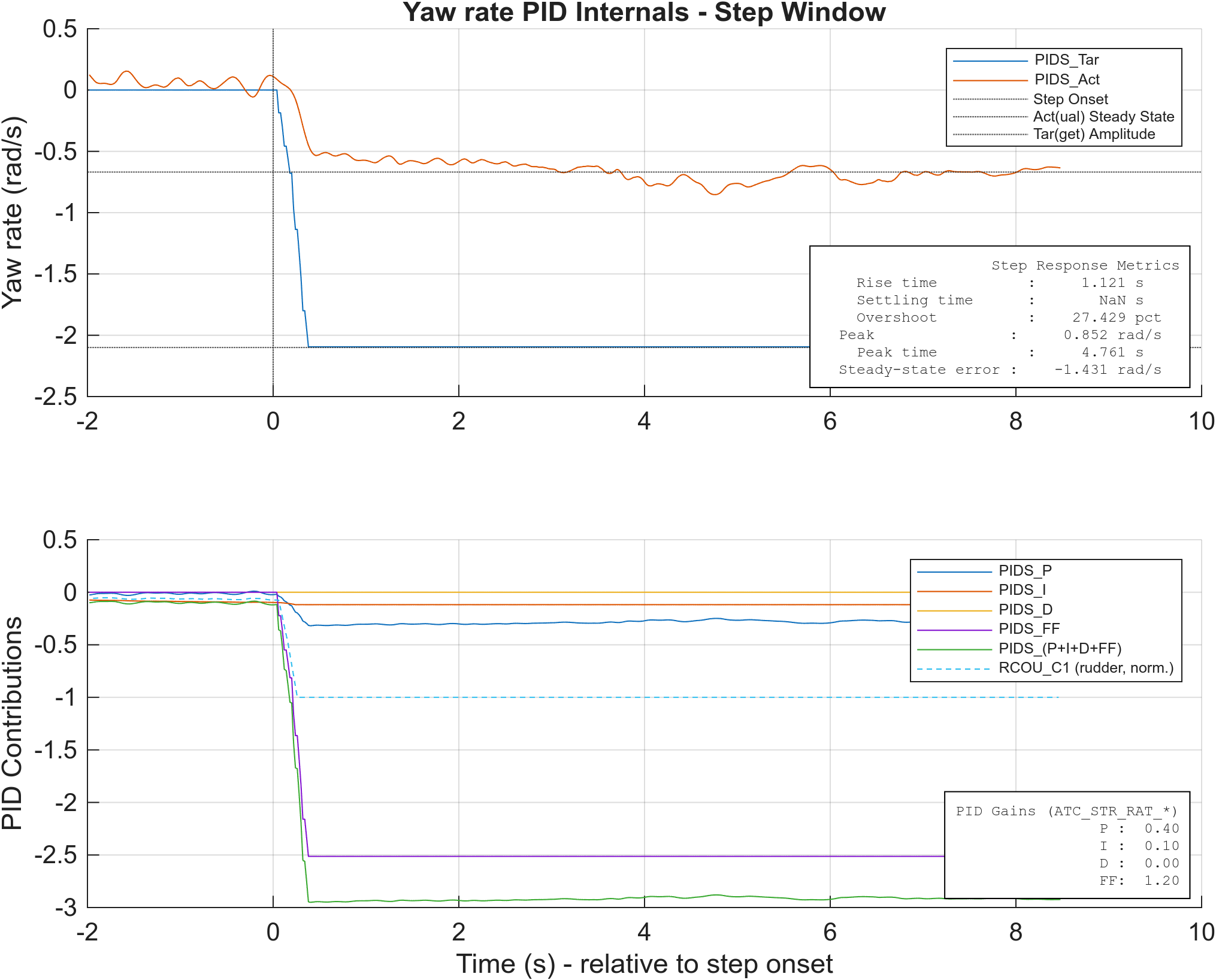
Tuned - Yaw-rate
Summary
Tuned PID gains and step-response metrics across the three experiments for both channels. Generated by closedloop_assess_main.m; the table content is included from metrics_summary.md, regenerated each time the analysis script runs.
| label | P | I | D | FF | RiseTime (s) | SettlingTime (s) | Overshoot (%) | SS Error |
|---|---|---|---|---|---|---|---|---|
| base_speed | 0.2 | 0.2 | 0 | 0 | 2.030 | 20.293 | 11.50 | 0.0000 |
| ff_speed | 0.2 | 0.2 | 0 | 0.2 | 2.791 | 10.079 | 0.53 | -0.0200 |
| tuned_speed | 0.4 | 0.1 | 0 | 0.2 | 5.521 | 10.139 | 0.44 | 0.1600 |
| base_yaw | 0.2 | 0.2 | 0 | 0 | 2.608 | NaN | 19.88 | 1.3014 |
| ff_yaw | 0.4 | 0.1 | 0 | 1.2 | 1.121 | NaN | 27.43 | -1.4310 |
| tuned_yaw | 0.4 | 0.1 | 0 | 1.2 | 1.181 | NaN | 30.04 | -1.3611 |